Session 5 Charges on the move --ELECTRICITY and ELECTRONICS
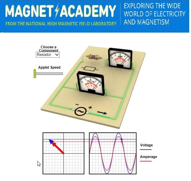
The internet has so many useful animations to explain this section, Electricity and Electronics, that it is difficult to point you to the BEST one. Your personal choice may well be different from the one I have given below but I'm sure you will enjoy this web site from the High Magnetic Field laboratory. I feel it will give you a good grounding in the fundementals of the subject - https://nationalmaglab.org/education/magnet-academy/watch-play
You may also like to use the analogy of flowing water.Texas Instruments produced a basic text "Understanding Solid State Electronics" using channels of water and one of their first diagrams is given below - it indicates that "charges on the move" behave in a similar manner to water flowing down a channel .
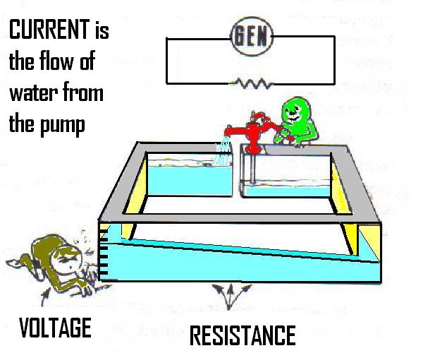
The channel along the front of our water circuit is narrow and this restricts the current flow. This is termed a RESISTANCE as it resists water flow and is shown in the circuit as a zig-zag line. If VOLTAGE is analogous to the water height, then there is a gradual decline of water level as we move from the left to right. If the "green" pump man were to stop pumping then the water would still flow until the same level is present in the whole channel. A resistance can of course be localized as in the next illustration:
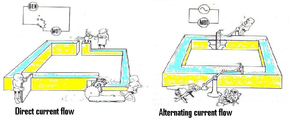
Some form of sluice gate is used to control the current which then powers a wood saw (left slide). The right hand slide shows another electrical circuit but this time there is an alternating current. Again, a sluice gate could control the current flow and a different sawing arrangement is used. This form of electricity is used in the home for lighting and heating though direct current is needed for most electronic gadgets,
.We are now in a position to appreciate a full "circuit" with our water channel -- the pump is the battery, the channels are the wires, the sluice gate could be a switch ( either fully IN for OFF or fully OUT for ON ) and another thin section of channel for, say, a light bulb ---- WOW !! a small step in understanding electricity.
Extensive simulations have been made for all manner of electrical devices and it is worth exploring textbooks and the web. Two other electrical components are in constant use along with batteries, resistors and switches, namely, inductances (sometimes called chokes) and capacitors (sometimes called condensers). An inductance is just a coil of wire and a capacitor is two conducting plates separated by a small distance from eachother. Between the plates there is usually a dielectric material (see session 3). Water models are given below:
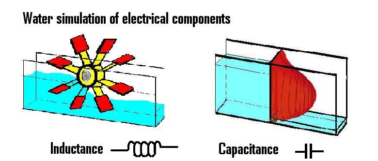
As seen the symbol for an inductor is just a coil of wire and it behaves like a paddle wheel. At switch on, in a dc circui, the paddle wheel will slowly start to revolve ( it has inertia) but after this initial period will give little resistance for a steady flow of current. At switch off, the paddle wheel still keeps going and can generate quite a high voltage. This is the principle of the induction coil which has, in the past, been of great use in the automotive industry. With an ac circuit the paddle wheel is constantly being driven from forward rotation to reverse rotation and offers considerable impedance to current flow.
The capacitor acts like a channel with a rubber diaphram across it. At switch on, in the dc circuit, current floods in initally but then the diaphram stops further flow and the capacitor will have the full battery potential across it. It is therefore a perfect device for storing charge. As we are not in a perfect world the diaphram may be a little "leaky" so that a small current may flow through. At switch off --- the voltage across the capacitor gradually falls due to the leakage current. Supercapacitors are now made which keep their charge for several years. In an ac circuit the capacitance does impede the current flow to a certain extent but the diaphram bulges on either side and so lets the current flow.
A good tutorial on dc circuits is available from the University of Guelph in Canada:
Circuit diagrams are given and the problems will help you to gain a better understanding of current flow -- www.physics.uoguelph.co/tutorials/ohm .
If we just consider a very simple circuit of a variable resistance connected to a battery:
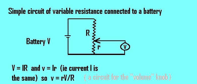
This would give us an output voltage in a range from V to zero. The theory , however, relies on the fact that the same current flows though each part of the resistance and therefore the voltmeter must not form another path for the current. Since most digital voltmeters have a high resistance (> 10 megohms) current flow in this pathway would be negligable.
The big question now is how do we deal with circuits that are AC , that is, our source is the little man waving a paddle forwards and backwards rather than our green man with a pump. In principle it is easy, all the theories that you have used for dc circuits can be used in ac BUT!! the components have to be given a COMPLEX (square root of minus one) identity. R is just the same so the potential divider that we have shown is exactly the same with both ac and dc. Thus, the comment about the volume knob holds true and every item of consumer electronics will have a "volume" knob to change the level of sound intensity. For the inductor we write the impedance as jwL where j is the square root of -1 and w is 2*PI*frequency.
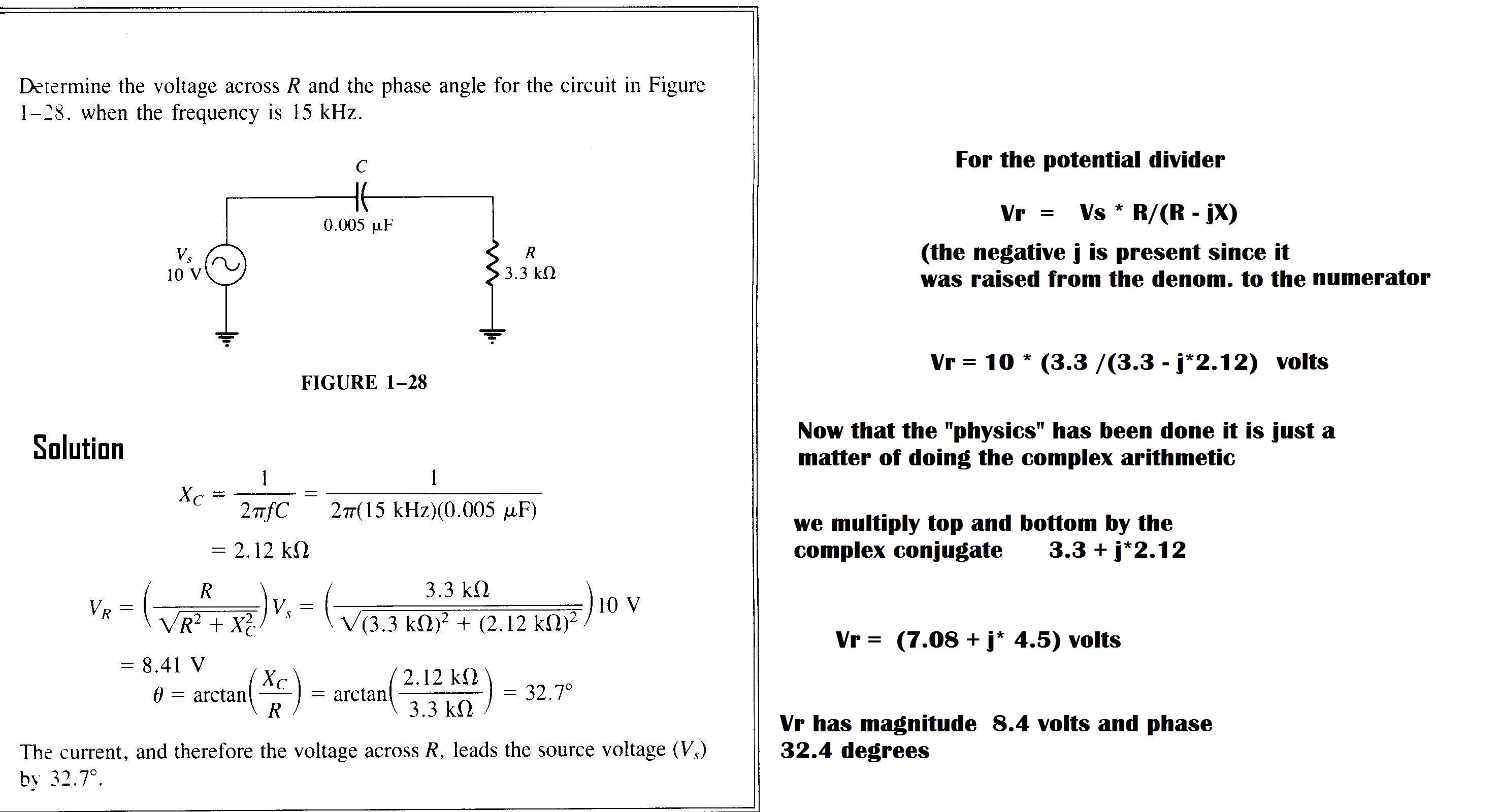
For a capacitor the impedance is given as 1/(jwC). Often textbook will mention the term "reactance, X" which has the unit of "ohms" and thus conforms more closely to resistance. For the inductance we have reactance = wL , for capacitance the reactance is 1/(wC) . A potential divider circuit will now be given:
Complex arithmetic is more time comsuming then the arithmetic done with real numbers but conceptually circuit analysis is just the same as for dc circuits. A textbook that I found very helpful was "An introduction to Electronics" by Dennis F. Shaw, Longmans 1962. The first chapters (1 to 8) explain complex circuit analysis very clearly and script notation is used for complex quantities. The last chapters (9 to 15) are less useful as they describe valves and transistors which may only be of historical interest now.
Widespread use of computers has given many useful tools in education. Software for simulating circuits started to become available in the early 1970's with , for example, SPICE (Simulation Program with Integrated Circuit Emphasis) being available in 1973. Many more have followed and I have found ACIRAN - a Circuit Analyser -- to be easy to use.
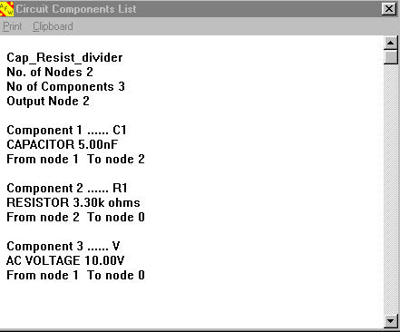
The components are entered with "values", "names" and "node positions" and then an analysis is carried out : eg a frequency scan can be made from 1Hz to 1 MHz with, say, 100 steps. The calculated data can be presented as a table or in graphics form as below:
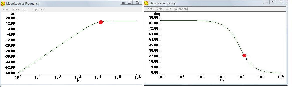
As one can see the calculated data is in agreement with the calculation made for frequency 15 kHz. ( note dB = 20* log10(V) ) . Perhaps a repeat calculation can be made for the capacitor-resistor divider at a frequency of 1 kHz to gain experience with complex calculations.
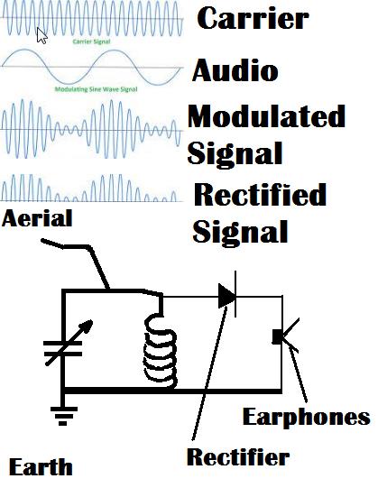
And now we are ready to see how a crystal set works --- my childhood mystery! A inductance and capacity are connected in parallel and this "so called" tuned circuit picks out waves from radio stations.
(By the way, there is an interesting watch on You Tube about early radio and it explains how a difficult it was to detect the signals)
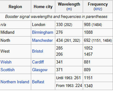
There were only a few avaible when I was searching with my crystal set, for example, Home Service transmitted on the following frequencies:
The crystal set was simple - a tuned circuit, a diode/ rectifier/ "the cat's whisker" and a pair of earphones. But WHAT MAGIC as the set was tuned into a "station" and the headphones gave out an audio signal .
Electronics has changed with breathtaking speed since the crystal set days and this is described in Physics Education vol40 2005, page 252. (the article is also included on a web-site www.methodbook.net - open "electronics" and click on 100 years. The file is downloaded and is highlighted on the bottom left of screen - just click to open)
A hundred years of Electronics - 1904 to 2004.
There is so much talk about the information age these days that one is apt to think that it has always been with us. Most people take mobile phones for granted and will tap into their home computer or visit a cyber cafe to keep in touch with their nearest and dearest. However, electronics, the key to this information age, started only 100 years ago and the pathway to our present position has been a long and tortuous but extremely exciting adventure.
1 Thermionic devices.
After Thomas Edison had invented the light bulb in 1878, John Ambrose Fleming, a professor in Electrical Engineering at University College, London, carried out further investigations into metal filaments in glass bulbs. Eventually he patented (in 1904) a device with two electrodes in the same glass envelope called a diode and this was to result in one of the most momentous journeys that mankind has ever made:
it was the evolution of electronics.
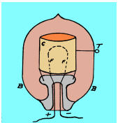
Fig 1 Diagrammatic form of the Fleming diode
In figure1 the normal filament of an Edison bulb is labelled as F and the
new electrode is the cylinder, C, which encases the filament. It is possible
to connect a wire to this latter electrode by the terminal, T. As in the
case of the Edison light bulb, the glass bulb, B, is evacuated. The remarkable
property of this device was that, although electrons could flow from the
Filament to the terminal T they could not flow in the opposite direction.
This was therefore what is known as a non-Ohmic device and the term "valve"
was soon introduced as an analogy to valves for controlling water flow. (Note.
In USA these thermionic devices are referred to as "tubes", short for vacuum
tubes.) An illustration of the device is shown in figure
2.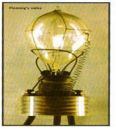
Figure 2 Photograph of the Fleming diode ( courtesy of the ULC Fleming collection )
So, why was this fairly primitive device such a timely arrival into the 20-century?
In 1896, Marconi first demonstrated the transmission and detection of radio waves as a means of communication without wires, i.e. "wireless". The weak link in his system was the, so called, coherer which had to detect minute electrical signals. Now, the Fleming diode was perfectly suited to detecting oscillating signals such as those of a radio signal. The positive part of the wave flows across the device and the negative part doesn't ( one can imagine a sine wave with the negative portions chopped off) and thus the ensuing direct output could readily be detected with sensitive galvanometers. With this increase in sensitivity the distance of wireless communication was vastly increased and the communications era was born.
It was not long after Fleming had constructed the diode that a third electrode was added to the valve and this produced the so called triode (Lee de Forest, 1906 ). This device was very versatile in that it could amplify electrical signals and so became the work-horse of early electronics. Later refinements give rise to the tetrode, three electrodes and the filament ( Hull 1919) and yet later the pentode (Jobst and Telegen 1926).
It is fair to say that in the late 1950's, i.e. more than half way through the 100 year period, the valve reigned supreme. There had been massive developments of electronic components during the World War II years and quality sound reproduction, radio, and TV was enjoyed by most of the population in the post-war years. In addition, the vast array of instrumentation that accompanied these developments put electronics at the forefront of both industry and commerce.
An illustration of a quality stereo amplifier from the late 50's is given in figure 3:
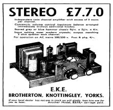
Figure 3 A stereo amplifier with valves mounted on an aluminium chassis
Despite the many successes of thermionic valves there was one field of studies where problems were arising. In the construction of digital computers a prodigious number of valves were necessary to provide storage and data manipulation. The ENIAC computer (initials stand for Electronic Numerical Integrator and Calculator and the computer was unveiled in USA in 1946) used 18,000 valves and these valves failed at a rate of approximately one every 10 minutes making successful operation somewhat intermittent. The Mark I computer developed by the Ferranti Company in UK had similar problems so the development of such computers into a Home Computer was a distant dream.
To pick up the story of computer development it is necessary to retrace our steps to the turn of the century once more.
2 Discrete solid-state devices.
In the early days of broadcasting a point metal contact pressed onto a semiconductor crystal, lead sulphide, was used as a detector for wireless waves. A fine wire was required to make the metal contact and it was likened to a "cat's whisker" so a cat's whisker radio was a gadget to be had at the time. The crystal detector was more sensitive then the coherer but much less reliable and, therefore, when the Fleming diode became available this detector ( and the coherer) was replaced by the thermionic diode. Whereas the basic theory of electron flow in evacuated valves was well understood at the turn of the 20th century, there was no adequate theory to show how electrons moved in solids and, in particular, semiconductors. Thus the cat's whisker diode development could not proceed with confidence and, in retrospect, it has meant that a large part of the 100 years of electronics has been devoted to the technology of valves which is largely irrelevant in modern day electronics.
Eventually, the Quantum Theory of solids was developed in the 1930's and this now opened the route to the development of what is known as solid-state electronics. The point contact transistor was announced to the world by Bardeen and Brattain in 1947 and is shown in figure 4:
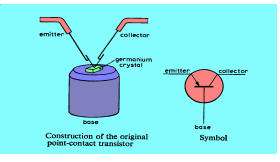
Figure 4 Diagram of a point contact transistor
An illustration of the above device is given in figure 5;
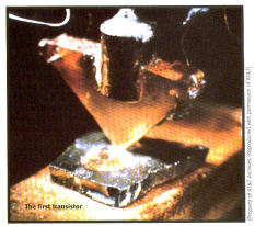
Figure 5 Photograph of the first point contact transistor ( Property of AT&T Archives. Reprinted ` with permission of AT&T)
The two critical points about the transistor were (a) that it was light and robust and that it did not require a heated filament to produce electrons and therefore (b) it consumed much less power then valves. The point contact device, shown above, was a little reminiscent of the cat's whisker diode and was not 100% reliable. However, the technology of diffusing impurity atoms into semiconductors was soon developed and a third advantage could be added to characterise transistors -(c) they offered reliability. Planar diffusion processes, in which diffusion occurs at only one surface, helped to create many different forms of the transistor.
( Incidentally, transistor circuits operate with low voltage supplies~ 5 to10V compared the valve circuits which require ~150 to 250V).
Using many of the design ideas introduced in the valve days, transistor circuits using discrete components (i.e. single resistors, capacitors, diodes, transistors, etc ) developed at a rapid pace and, radio receivers, once bulky and heavy, could be manufactured as lightweight portable items. This dramatic reduction in weight was partly due to the compactness of the circuit layout on printed circuit board (for more details see www.methodbook.net/electronics ) as compared to the aluminium "chassis". This latter type of construction is illustrated in figure 3 with valves being secured in a large aluminium base of the stereo amplifier. Battery weight was also a large saving in that the low power requirement of a transistor circuit, typically a few milliwatts, could be supplied by, say, four size AA, 1.5 Volt batteries.
3 Integrated circuits.
In little more than ten years after the transistor had been announced, Kilby (1959) filed a patent for the production of integrated circuits ( IC's). In much the same way as the jet engine revolutionised aviation, that successful laboratory demonstration of an IC by Jack St Claire Kilby on 12th September 1958 was to change electronics for ever. Using the planar process, all manner of components (diodes, resistors, transistors, etc) could be fabricated adjacent to each other on the same piece of semiconductor with masks to define the areas to be diffused. Then, by interconnection through a metallization procedure, a complete circuit could be fabricated on a semiconductor wafer. Thus, the laborious connection of thousands of discrete components by soldering, with its attendant lack of reliability, was carried out by a machine and relatively few connections were left to be made on a PCB. So, after Kilby, any limitations to the complexity of electronic circuits was largely due to constraints of imagination rather than to those of technology.
A typical wafer containing IC's is shown in figure 6 and an account of early developments of IC technology is given at www.orc.soton.ac.uk/about/earlydays/sims.php )
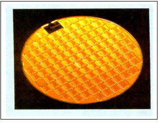
Figure 6 Many integrated circuits (IC's) fabricated on a silicon wafer.(Courtesy of Ferranti Co)
Each small element on the semiconductor slice (usually silicon - hence the term silicon chip) is a complete circuit and after cutting and mounting on a suitable terminal base is ready for use.
The dramatic size reduction, which accompanied transistor circuits, was dwarfed by the IC revolution and whole instruments were reduced to a single chip. For instance, the author used a 10 MHz frequency counter ( Marconi Type TF1345 ), which was a product from the "valve days", and the complete functionality of this Marconi instrument was replaced by a 28 pin counter chip, type IC 7216 from Intersil. At this time the so called Large Scale Integration was rapidly giving way to Very Large Scale Integration and, as geometrical sizes of components on the chip were reduced, the speed of operation of the chip was increasing and all at a lower cost!
In the early days of IC development it was noted by Gordon E. Moore, director at Fairchild Incorporated, that the complexity of IC's doubled every year. His predictions, now blessed with the name Moore's Law, has proved to be remarkably correct over the decades which have followed.
So, electronics in its integrated form was now in fast forward mode and all branches of the subject were to benefit from this rapidly changing technology. In particular, the manufacture of computers made rapid advances. In 1960 the Minicomputer PDP1 was introduced by Digital Equipment Incorporated and it was to be followed rapidly by other PDP models. The PDP8 was the first minicomputer to sell for less than £10,000 and therefore a computer for the home was beginning to come into sight.
The first microprocessor, which was basically a whole computer on a chip, (model number 4004), was launched by Intel in 1969 and it is the microprocessor that has brought computers into our homes.
4 Home Computing
From the 1970's to the present date one has witnessed remarkable developments in electronics with scientific, military and commercial interests driving the industry forward. One cannot possibly describe all the facets of this huge industry or determine the extent to which the silicon chip has changed people's lives so only a brief examination will be made into one topic area, namely, that of home computers.
(For more information about general electronics see:- www.ieee.org/organizations/history_center/milestones_listhtml .
Perhaps the division of the above thirty-year period into decades will help in our telling of the home computer story.
The 1970's were very much involved with developments of the microprocessor families. The Intel 4004 had a 4-bit instruction and data word length and therefore had limitations in data manipulation and memory addressing. By 1974 Intel had introduced the 8-bit processor 8008 but there were other companies in the semiconductor processing business; Fairchild, Texas, RCA, National Semiconductors, Zilog and Mostek who were all producing microprocessor chips. In the late1970's these chips were finding their way into computers, for example, Apple, TRS80, Commodore PET, Sinclair ZX80/81 and Acorn BBC computers to name but a few.
Features of the earlier transistor technology, such as small size, low power, good reliability, were translated to integrated circuit technology but advantages of low cost became evident, also. Since the fabrication of an IC chip is completely automated, very complex circuits could be produced at low cost provided the quality control of processing was of a suitable standard.
In the 1980's IBM joined in the race. IBM, the world's largest computer company of the day, entered the desk top computer market in a somewhat half-hearted way, possibly, believing that it would be more of a hobbyist's fad then a serious competitor to commercial computing. The IBM Personal Computer (PC) was launched in 1981 and was based on the Intel 8086 processor. Using a "ready-made" processor was a serious departure from IBM's normal strategy in that it would normally develop a critical component, such as a processor, in house so that design security would be maintained. Not only did IBM "farm out" manufacture of the processor but it commissioned Bill Gates of Microsoft to develop an operating system called MS-DOS ( Microsoft Disk Operating System) for the PC. A year later in 1982 IBM launched an improved model called the IBM Personal Computer-AT (Advanced Technology) and published many details of this new design. It was only a matter of time before IBM clones appeared since any company could build the computer with the circuit details provided by IBM and purchase the processor chip and software directly from Intel and Microsoft, respectively. Evidently, exclusivity of patent rights had not been obtained by IBM for either processor or operating system software. The benefit to the consumer was the availability of a sophisticated cloned PC computer at a fraction of the cost which IBM would have charged. The PC home computer was to dominate the world from this moment in history.
In the 1990's the story of home computing has broken all limits of excellence. Data links with the Universal Serial Bus (USB) and modems has enabled the home computer to be connected to the world in a manner impossible to envisage 100 years ago when Fleming was developing his diode. Indeed, the decade has given rise to exceptional developments in processor capability and software provision and, unquestionably, the story of the PC, as it links into other media areas, has much further go.
There is no doubt that the modern PC has impressed today's generation with its versatility, speed and low cost but another device will be mentioned to show what a varied subject electronics has become. Early in 2002, Zarlink Semiconductors introduced their M2A capsule endoscope (more details at www.capsuleendoscopy.org ). This pill-sized capsule, which passes naturally through the digestive tract, incorporates a miniature camera, LED-based flash, Radio Frequency transmitter chip and two batteries. During the course of its passage, the camera takes two high-resolution colour images per second of the digestive tract. These are relayed to a data recorder in a belt worn by the patient who can carry out his/her normal daily routine. The M2A is, very much, an example of extreme circuit miniaturization operating at microscopic power levels and, undoubtedly, will be of great benefit to medicine.
It is, however, just one device amongst thousands that are being manufactured in the electronics industry of today. With such a picture of the recent past, the future can only lead to even more exciting times, so,
********************************
An informative web page has been produced by Andrew Wylie about the early days of transistors
-- typically the OC 70 (germanium), click here.
For the practicalities of electronics I must direct you to an excellent article ----- "The Scots Guide to Electronics" which has been produced at St Andrew's University.
www.st-andrews.ac.uk/~www_pa/Scots_Guide/intro/electron.htm
The maximum enjoyment of electronics is gained from a "hands-on" approach -- try to construct a circuit no matter how simple and be amazed at your handywork.
Also - you can sample one of the OU lectures 271